
A Beginner's Guide To CNC & Laser Cutting with PhysBox Etch
How to transform digital vector designs into physical wood, acrylic, and brass parts with safety, kerf compensation, and precision.
1. The Subtractive Mindset & Why CNCs Don't Forgive Lies
Welcome to the satisfying, noisy, and occasionally terrifying realm of subtractive manufacturing. If you come from the gentle world of 3D printing, you are accustomed to an additive hotend that patiently squirts molten PLA onto a glass bed. If a 3D printer makes a mistake, it leaves a harmless blob of plastic string.
A CNC router or high-power laser cutter, by contrast, operates with uncompromising physical force. It spins a hardened tungsten carbide cutter at 18,000 RPM or focuses a 40-watt CO₂ laser beam down to a 0.1mm kerf spot. It does not care if that material is 18mm Russian Birch Plywood, anodized aluminum, or your favorite aluminum workpiece hold-down clamp. If your code tells the tool to plunge 20mm deep into solid stock at 5,000 mm/min, it will cheerfully try to do so until either the stepper motor stalls, the bit snaps, or your circuit breaker trips.
In 3D printing, mistakes cost 4 cents of filament. In CNC milling, mistakes cost a $35 end mill, a ruined piece of hardwood, and 45 minutes of picking wooden splinters out of your hair.
PhysBox Etch was designed specifically to bridge vector artwork with real CNC machine control without requiring a degree in mechanical engineering. It gives you a bed-accurate 2D design workspace, automatic derived speeds and feeds, real-time safety warnings, and live GRBL machine control over WebSerial.
2. Grid, Stock & Coordinates ($H vs G54)
Before touching a cutter, you must understand where your machine thinks it is in 3D space. CNC machines operate on two distinct coordinate systems:
- Machine Coordinates (MPos): Set when you home your machine (
$H) against physical limit switches. Machine (0,0,0) is usually the back-right corner with the spindle pulled all the way up. - Work Coordinates (WPos / G54): The temporary local coordinate frame tied to your physical wooden stock. The bottom-left surface corner of your plywood is Work Zero (0,0,0).
Setting Up Your Bed Bounds in Etch
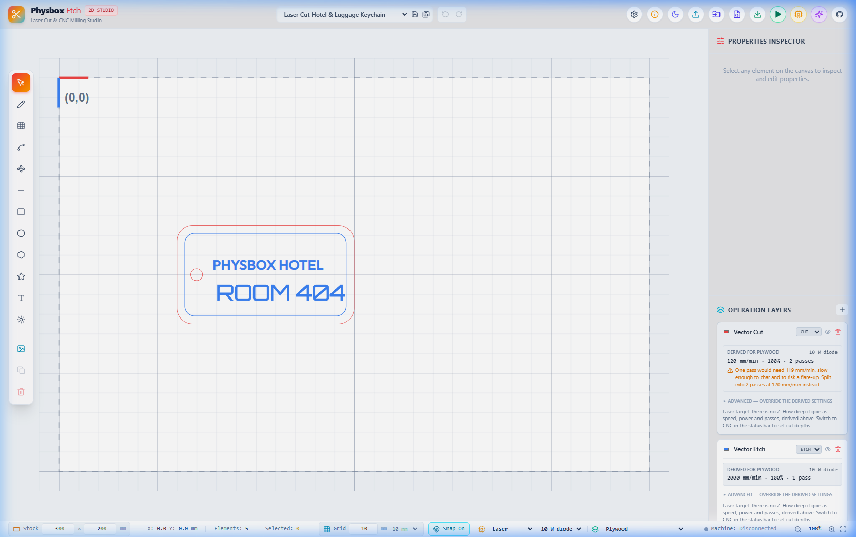
At the bottom bar of PhysBox Etch, set your exact physical stock size (e.g. 300mm x 200mm). The canvas updates immediately, displaying red and blue origin marker arrows at (0,0). Always align your physical stock on the CNC bed so the front-left corner matches the (0,0) origin on the Etch screen.
Leave a 15mm margin around your vector artwork. Never place cuts right along the boundary edge unless your workpiece is held down by double-sided tape or vacuum rather than mechanical corner toe-clamps.
3. Tooling & Derived Feeds and Speeds
Picking the right cutting bit (end mill) and setting the correct spindle RPM / feed speed determines whether your cut sounds like a gentle hum or a screeching air-raid siren.
Upcut Spiral End Mill
Pulls wooden chips upward out of deep slots. Excellent for plywood pockets, but can leave minor fuzz on the top veneer.
Downcut Spiral End Mill
Pushes wood chips downward. Leaves a pristine, razor-sharp top surface on veneered hardwoods and plywood.
Compression Spiral
Combines upcut and downcut flutes for clean edges on both top and bottom faces of laminated sheets.
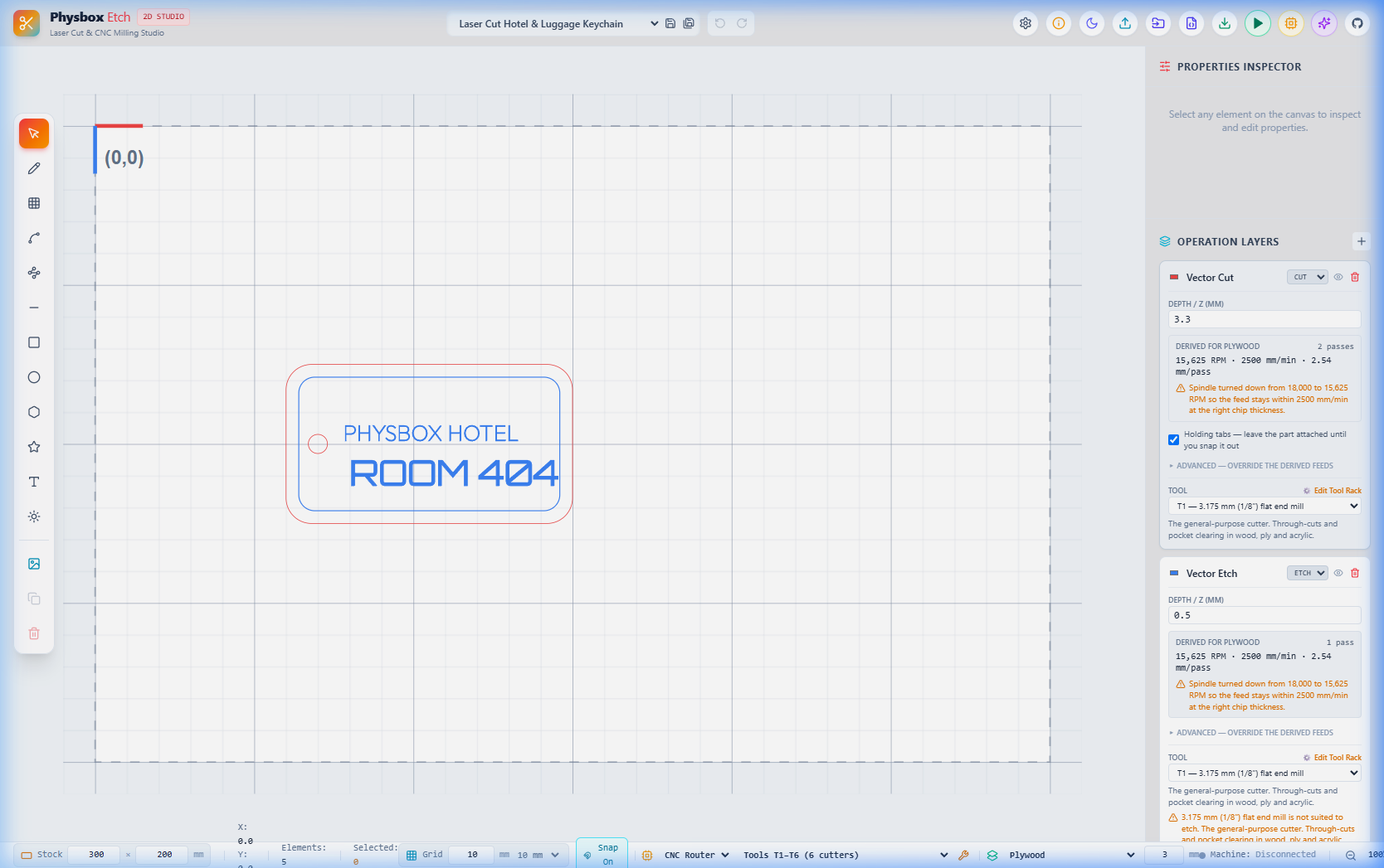
Etch calculates chip load automatically based on cutter diameter and material presets (Plywood, MDF, Acrylic, Hardwood). If you select 18,000 RPM in Plywood, Etch will warn you: "Spindle turned down to 15,625 RPM so feed stays within 2500 mm/min at the right chip thickness."
4. Depths, Multi-Pass Stepdown & Holding Tabs
Never cut through 12mm plywood in a single heroic pass! Doing so creates massive tool deflection and will likely snap your carbide end mill. Instead, use multi-pass stepdowns:
- Stepdown Depth: Cut in layers of 1.5mm to 3.0mm per pass depending on bit diameter (rule of thumb: maximum pass depth = 50% to 100% of bit diameter).
- Holding Tabs: When cutting out a closed perimeter part, leave 2 to 4 small tabs (e.g.
4mm wide x 1.5mm thick) so the finished part stays anchored to the waste stock until the job finishes.
5. Touch-Plate Z Probing & 3×3 Bed Heightmaps
Accurate Z zeroing is the difference between a pristine cut and a gouged spoilboard. PhysBox Etch includes direct WebSerial touch-plate probing routines:
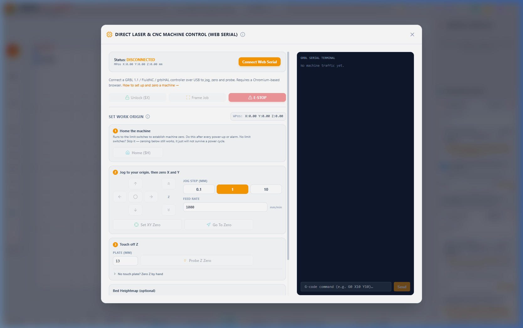
- Attach the ground alligator clip to your metal CNC collet/cutter and place the aluminum touch plate flat on top of your material.
- Open the Run / Machine Control Panel in Etch, enter touch plate thickness (e.g.
13.00 mm), and click Probe Z Zero. - The spindle slowly descends until electrical continuity is triggered, immediately zeroing your Z work coordinate with sub-millimeter precision.
6. 3D Toolpath Preview & Live WebSerial Streaming
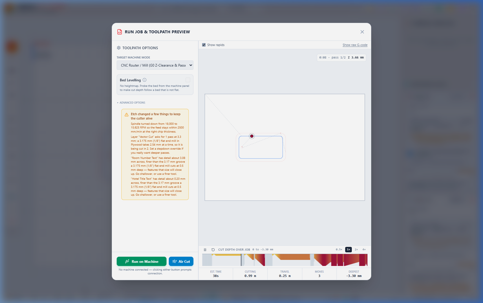
PhysBox Etch streams G-code directly over USB WebSerial (supported in Chrome, Edge, and Opera). Connect your laptop to your GRBL 1.1, FluidNC, or grblHAL controller board.
7. The Post-Mortem Guide: What Went Wrong?
Every CNC machinist and laser crafter makes mistakes. Here is how to diagnose the top shop floor issues:
Spindle Stalls / Loud Screech
Cause: Pass depth is too deep or feed rate is too fast.
Fix: Back the feed off with Live Trim — it acts on the motion already buffered, so you do not lose the job. If it is still screeching, E-STOP, halve the stepdown in the Etch layer panel and re-run.
Charred / Blackened Wood
Cause: Spindle RPM is too high relative to feed speed (friction burn).
Fix: Nudge feed up or spindle down with Live Trim mid-job until the burning stops, then save that pair into the layer for next time.
Rounded Inside Corners
Cause: A round 3.175mm end mill cannot cut sharp 90° inside corners on mating box tabs.
Fix: Use Dogbone or T-bone corner reliefs in your vector design.
You now possess the foundational knowledge to turn raw lumber into precision carved parts with PhysBox Etch. Remember: zero your Z properly, use holding tabs, wear eye protection, and enjoy the magical craft of making!